SAJ HS3 via Modbus RTU (RS-485)
This guide describes step by step how to connect a SAJ HS3 battery system to the Currentt Navigator via Modbus RTU over RS-485.
✅ Compatible models
Single-phase (HS3-S2 series)
| Model | Power |
|---|---|
| HS3-3K–6K-S2 | 3 – 6 kW |
Three-phase (HS3-T2 series)
| Model | Power |
|---|---|
| HS3-3K–12K-T2 | 3 – 12 kW |
🧰 Requirements
- Currentt Navigator Pro (with RS-485 Modbus connection)
- RS-485 cable (twisted pair, e.g. CAT5 or a suitable 2-wire cable)
- Phillips screwdriver (for access to the communication port)
⚠️ Safety warnings
Always switch off the system before making the communication connection. Set the DC switch to OFF and switch off the AC side via the distribution board. Wait at least 5 minutes for the capacitors to discharge.
1️⃣ Step 1: Switch off the system
- Set the DC switch on the HS3 to OFF
- Switch off the AC side via the distribution board (circuit breaker)
- Wait at least 5 minutes for the capacitors to discharge
- Check that the HS3 display is off
2️⃣ Step 2: Connect the RS-485 cable
The RS-485 connection is located on the communication connector of the SAJ HS3.
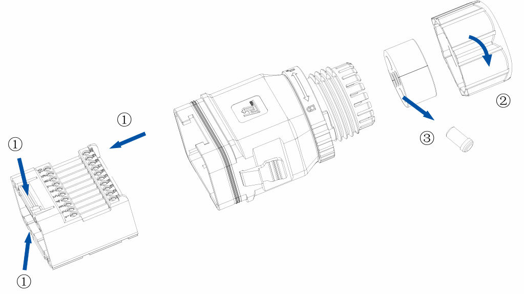
- Remove the communication connector from the HS3
- Loosen the swivel nut (②) and remove the sealing plug (③) from the cable gland
- Lead the RS-485 cable through the cable gland
- Remove the terminal block (①) from the connector
- Connect the RS-485 cable to the terminal block:
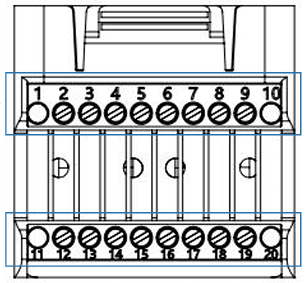
| Pin | Signal | Description |
|---|---|---|
| 11 | RS485_A (Data+) | Non-inverting (positive) |
| 12 | RS485_B (Data−) | Inverting (negative) |
- Insert the terminal block back into the connector
- Connect the other end to the RS-485 Modbus connection on the Currentt Navigator (A to A, B to B)
- Tighten the swivel nut
- Reattach the communication connector to the HS3
Ensure that the A and B connections are wired correctly. Swapping A and B will cause communication errors.
Connect the ground (GND) on one side only: either to the Currentt Navigator or to the device — but never on both sides. Connecting ground on both sides can cause a ground loop, leading to communication errors.
3️⃣ Step 3: Switch on the system
- Switch on the AC side via the distribution board
- Set the DC switch on the HS3 to ON
- Wait for the display to start up
4️⃣ Step 4: Configure communication
The communication settings are configured via the LCD display on the HS3 or via the eSolar app.
Via the LCD display
- Navigate on the display to System Settings
- Go to Communication Settings
- Set the following values:
| Setting | Value |
|---|---|
| RS-485 Address (Modbus ID) | 1 (default) |
| Baud rate | 9600 |
| Protocol | Modbus RTU |
- Confirm the settings
Via the eSolar app
- Connect to the HS3 via WiFi or Bluetooth
- Go to Advanced Settings > Communication
- Set the Modbus address and baud rate
5️⃣ Step 5: Configuration in the Currentt Navigator
After connecting and configuring the HS3, the system must be added in the Currentt Navigator.
Via the Setup Wizard (recommended)
- Click the settings icon (top right of the screen)
- Choose Setup Wizard
- Follow the on-screen steps
Manual configuration
- Click the settings icon (top right of the screen)
- Go to Components
- Click the + button in the Batteries section
- Select SAJ
- Enter the connection details:
| Parameter | Value |
|---|---|
| Connection | Modbus RTU (RS-485) |
| Modbus address | 1 (default) |
| Baud rate | 9600 |
| Data bits | 8 |
| Parity | None (N / disabled) |
📋 Settings summary
| Parameter | Value |
|---|---|
| Connection | RS-485 (Modbus RTU) |
| Protocol | Modbus RTU |
| Modbus address | 1 (default) |
| Baud rate | 9600 |
| Data bits | 8 |
| Parity | None (N / disabled) |
🛟 Troubleshooting
| Problem | Possible cause | Solution |
|---|---|---|
| No connection | A and B swapped | Check the polarity of the RS-485 connection (pin 11 = A, pin 12 = B) |
| No connection | Wrong Modbus address | Check the Modbus address on the HS3 display |
| No connection | Wrong baud rate | Check that the baud rate matches (default 9600) |
| No connection | Cable too long or damaged | Use a shorter cable or check for damage |
| Unreliable communication | No termination | Place a 120Ω termination resistor at the end of the RS-485 bus |
| No communication | System in sleep mode | The system may not communicate when there is no PV production (depending on firmware) |