Huawei inverter via Modbus RTU (RS485) connection
This guide describes step by step how to connect a Huawei SUN2000 inverter to the Currentt Navigator via Modbus RTU over the RS485 port (COM connector).
Modbus RTU via RS485 is only possible when there is no Huawei WLAN-FE Smart Dongle installed on the inverter. Is a dongle present? Use Modbus TCP instead.
See also: For connection via the local network (Ethernet), refer to the Huawei Modbus TCP guide.
✅ Compatible devices
Single-phase inverters
| Model | Power |
|---|---|
| SUN2000-2KTL–6KTL-L1 | 2 – 6 kW |
Three-phase inverters
| Model | Power |
|---|---|
| SUN2000-3KTL–10KTL-M1 | 3 – 10 kW |
| SUN2000-12KTL–20KTL-M2 | 12 – 20 kW |
| SUN2000-12KTL–25KTL-M5 | 12 – 25 kW |
🧰 Requirements
- Currentt Navigator
- CAT5 or CAT6 cable (UTP)
- Huawei FusionSolar app (iOS/Android)
- Smartphone
⚠️ Safety warnings
Always turn off the inverter before disconnecting the COM connector. Set the AC and DC switches to OFF and wait at least 5 minutes to allow the capacitors to discharge.
1️⃣ Step 1: Turn off the inverter
- Set the AC switch to OFF
- Set the DC switch to OFF (if present)
- Wait at least 5 minutes (capacitors discharging)
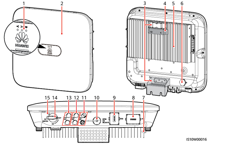
Huawei SUN2000 inverter: the COM connector is located at the bottom
2️⃣ Step 2: Disconnect the COM connector
The RS485 connection is located on the COM connector at the bottom of the inverter. The COM connector is a round, multi-pin connector.
- Unscrew the locking ring of the COM connector
- Carefully pull the connector out of the inverter
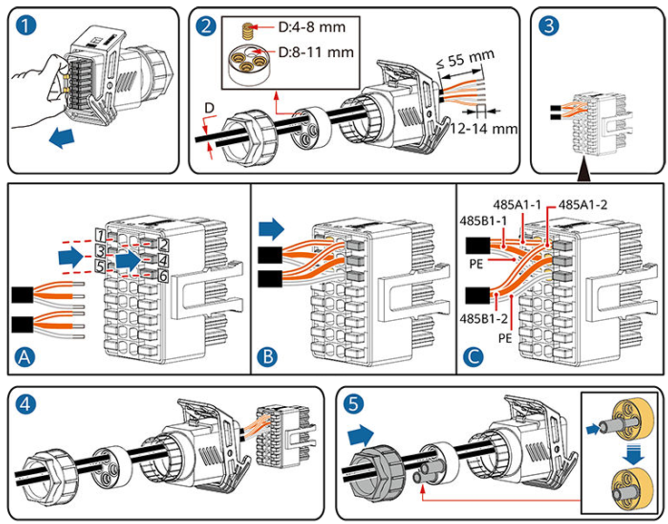
Disconnecting the COM connector, connecting the cable, and reinstalling
3️⃣ Step 3: Connect the cable
Use a standard CAT5 or CAT6 (UTP) cable. On the inverter side, cut off the RJ45 connector and strip the individual wires.
Always use a twisted pair for the A and B signal lines. The twisting of the wire pair suppresses electromagnetic interference (EMI) and is essential for a reliable RS485 connection.
Pinout single-phase inverter (SUN2000-L)
The COM connector on the single-phase inverter has 8 pins:
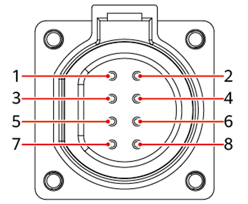
COM connector pinout SUN2000-L (single-phase): use pin 1 (RS485A) and pin 2 (RS485B)
| Pin | Function |
|---|---|
| 1 | RS485A (+) |
| 2 | RS485B (-) |
| 3 | Not used |
| 4 | Not used |
| 5 | Not used |
| 6 | Not used |
| 7 | Not used |
| 8 | Not used |
Connect the cable to pin 1 (RS485A) and pin 2 (RS485B).
Pinout three-phase inverter (SUN2000-M)
The COM connector on the three-phase inverter has 16 pins:
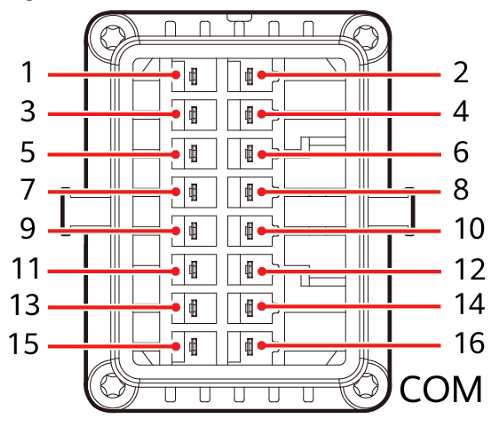
COM connector pinout SUN2000-M (three-phase): use pin 1 (RS485A) and pin 3 (RS485B)
| Pin | Function |
|---|---|
| 1 | RS485A (+) |
| 2 | Not used |
| 3 | RS485B (-) |
| 4 | Not used |
| 5-16 | Not used |
Connect the cable to pin 1 (RS485A) and pin 3 (RS485B).
On the three-phase inverter, RS485B is on pin 3 (not pin 2 as on the single-phase). Always verify the pinout for your model.
Wiring
| Wire color (T-568B) | Function |
|---|---|
| Blue | RS485A (+) |
| Blue/white | RS485B (-) |
You can also use other wire pairs, as long as you use a twisted pair and are consistent on both ends. The blue/blue-white pair is the standard choice.
Connecting to the Currentt Navigator
The Currentt Navigator has an RS-485 Modbus connector with three pins: A+, B-, and G (ground).
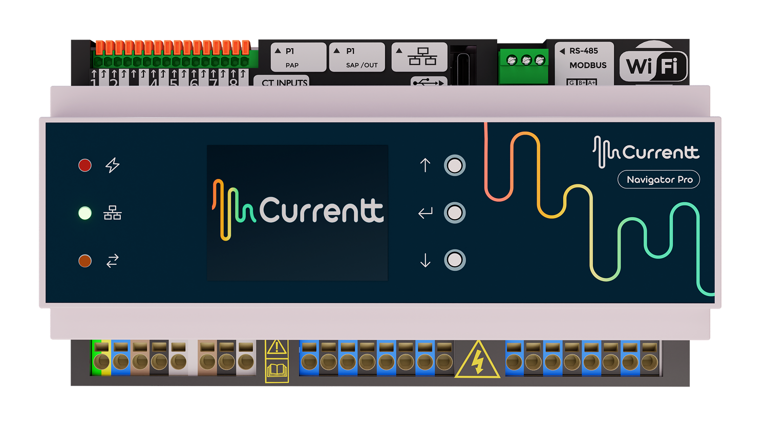
Currentt Navigator Pro: the RS-485 Modbus connector is located at the top right
Connect the other end of the cable to the RS-485 terminal block on the Currentt Navigator:
| Wire color (T-568B) | Currentt Navigator pin | Inverter COM pin |
|---|---|---|
| Blue | A+ | RS485A (+) |
| Blue/white | B- | RS485B (-) |
Connect the ground on one side only: either to the Currentt Navigator or to the inverter — but never on both sides. Connecting ground on both sides can cause a ground loop, leading to communication errors or equipment damage.
4️⃣ Step 4: Reinstall the COM connector and power on
- Reinstall the COM connector into the inverter
- Tighten the locking ring
- Set the DC switch to ON
- Set the AC switch to ON
- Wait for the inverter to start up (this may take a few minutes)
5️⃣ Step 5: Configure the inverter
Verify that the RS485 Modbus settings are correctly configured via the Huawei FusionSolar app.
Connect to the inverter
- Download the Huawei FusionSolar app on your smartphone (iOS/Android)
- Connect your smartphone to the inverter's WiFi hotspot
- Open the FusionSolar app and choose manual connection
- Log in as installer with the default password 00000a
Turn off your smartphone's mobile data, otherwise the inverter will not be found by the app.
Password: Has the password been changed? Reset the password according to the Huawei manual. Always ask the owner's permission before resetting a password.
Check RS485 settings
Navigate in the FusionSolar app to:
Settings >> Communication configuration >> RS485_1
Verify the following settings:
| Setting | Value |
|---|---|
| Baud Rate | 9600 |
| Protocol Type | Modbus |
| Com Address | 1 |
| Bus Frame Capture | 1 |
6️⃣ Step 6: Configuration in the Currentt Navigator
After physically connecting and configuring the inverter, the device must be added in the Currentt Navigator. This can be done in two ways:
🪄 Via the setup wizard (recommended)
- Click the settings icon (top right of the screen)
- Choose Setup Wizard
- Follow the on-screen steps
The setup wizard guides you step by step through the complete configuration process.
Is there a battery connected to the inverter (e.g. LUNA2000)? Indicate this when the setup wizard asks. This question will automatically appear during the steps.
⚙️ Manual configuration
- Click the settings icon (top right of the screen)
- Go to Components
- Is there a battery connected to the inverter?
- Yes → Click the + button in the Batteries section
- No → Click the + button in the Inverters section
- Select Huawei
- Indicate which phase the inverter is connected to (L1, L2, or L3)
- Under Communication, select Modbus and click RS-485
- Set the communication parameters:
| Parameter | Value |
|---|---|
| Baud Rate | 9600 |
| Data Bits | 8 |
| Parity | None |
| Stop Bits | 1 |
| Modbus address (Device ID) | 1 |
🔗 Connecting multiple inverters (daisy-chain)
If there are multiple Huawei inverters at the same location, you can connect them in series (daisy-chain) via RS485:
- Connect the first inverter to the Currentt Navigator via the COM connector (as described above)
- Connect the next inverter via RS485 on the same bus
- Give each inverter a unique Com Address (1, 2, 3, etc.)
In practice, we recommend connecting no more than 10 inverters in series for reliable communication.
🔗 Bus topology
Preferably use a daisy-chain (series) topology for the RS485 bus. For short distances (< 25 meters), a star topology often works as well. Connect a maximum of 32 devices to a single RS485 bus.
🔚 Termination resistor
For an RS485 connection, a termination resistor (120 Ohm) must be present at both ends of the bus to prevent signal reflections.
Currentt Navigator
The Currentt Navigator has a built-in termination resistor that can be enabled or disabled via software. By default, it is enabled. For a direct connection between a single inverter and the Currentt Navigator, no changes are needed.
Inverter
Check the inverter manual for whether a built-in termination resistor is present and how to activate it. The termination resistor must be active on the last inverter in the chain (or the only inverter).
🛟 Troubleshooting
| Problem | Possible cause | Solution |
|---|---|---|
| No communication | Smart Dongle is installed | Remove the dongle and use RS485, or use Modbus TCP |
| No communication | Wiring A/B swapped | Swap the A and B wires |
| No communication | Protocol not set to Modbus | Check the RS485_1 settings via the FusionSolar app |
| No communication | Wrong Com Address | Check that the Com Address matches in the inverter and Navigator |
| No communication | Wrong pins (single-phase vs. three-phase) | Check the pinout: single-phase = pin 1+2, three-phase = pin 1+3 |
| Intermittent communication | Poor cable connection | Check that wires are securely fastened in the COM connector |
| Intermittent communication | Cable too long (>1000m) | Use a shorter cable or an RS485 repeater |
| Timeout errors | Wrong baud rate | Ensure the baud rate is 9600 on both sides |
📋 Settings summary
| Parameter | Value |
|---|---|
| Physical port | COM connector (RS485) |
| Protocol | Modbus |
| Modbus address (Com Address) | 1 (unique per inverter) |
| Baud Rate | 9600 |
| Data Bits | 8 |
| Parity | None |
| Stop Bits | 1 |
| Bus Frame Capture | 1 |
| Cable | CAT5/CAT6 UTP (twisted pair) |
| Single-phase pins | Pin 1 (RS485A) + Pin 2 (RS485B) |
| Three-phase pins | Pin 1 (RS485A) + Pin 3 (RS485B) |
| Smart Dongle | Must NOT be installed |