SolarEdge inverter via Modbus RTU (RS485) connection
This guide describes step by step how to connect a SolarEdge inverter to the Currentt Navigator via Modbus RTU over the RS485-2 port. The inverter is configured to use the SunSpec protocol.
Always use the RS485-2 port on the SolarEdge inverter for the connection to the Currentt Navigator. The RS485-1 port is reserved for communication with a SolarEdge StorEdge battery (if present).
See also: For connection via the local network (Ethernet), refer to the SolarEdge Modbus TCP guide.
✅ Compatible devices
Single-phase inverters
| Model | Type | Configuration via |
|---|---|---|
| SE2200H - SE6000H | HD-Wave (compact) | SetApp |
| SE3000H - SE10000H | Home Wave | SetApp |
| SE3500 - SE6000 | Older models with display | LCD Display |
Three-phase inverters
| Model | Type | Configuration via |
|---|---|---|
| SE3K - SE33.3K | Three-phase | LCD Display / SetApp |
| SE5K - SE16K | Home Hub (three-phase) | SetApp |
Hybrid / StorEdge inverters
| Model | Type | Configuration via |
|---|---|---|
| StorEdge Single-phase | Hybrid with battery | SetApp / LCD Display |
| StorEdge Three-phase | Hybrid with battery | SetApp / LCD Display |
| SE5K-SE10K Home Hub | Hybrid with Home Battery | SetApp |
🧰 Requirements
- Currentt Navigator
- CAT5 or CAT6 cable (UTP)
- Phillips screwdriver or hex key (depending on the inverter)
- SolarEdge SetApp (for modern inverters)
- Smartphone with WiFi (for SetApp)
⚠️ Safety warnings
Always turn off the inverter before opening the enclosure. Set the ON/OFF/P switch to OFF and wait at least 5 minutes to allow the capacitors to discharge. Also turn off the AC side via the consumer unit.
1️⃣ Step 1: Open the inverter
The RS485-2 connection is located on the communication board inside the inverter. You need to open the enclosure to access the connector.
The communication gland (cable gland) is located at the bottom of the inverter. Below you can see the bottom of various SolarEdge inverter models:
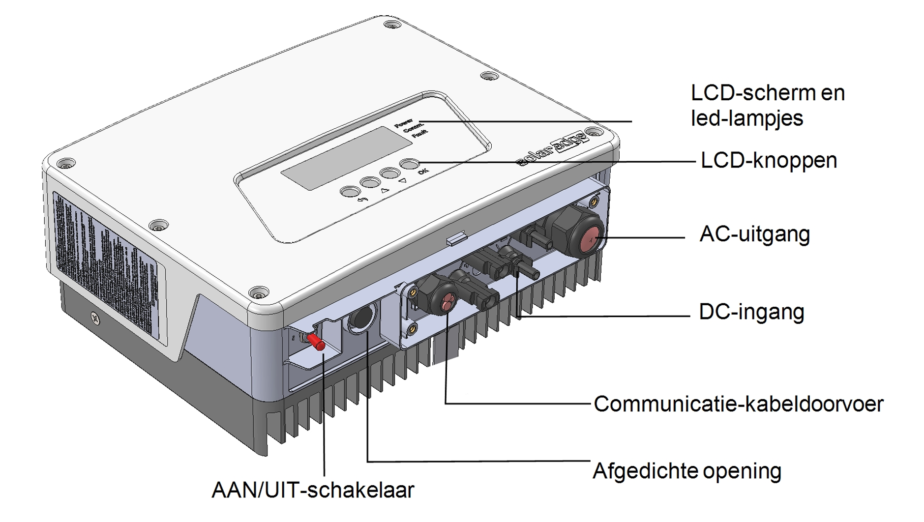
Single-phase inverter with LCD screen (older model): the communication cable gland is located at the bottom
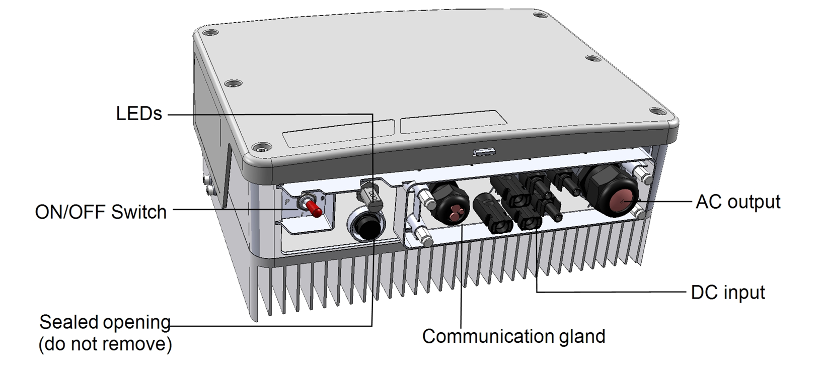
Single-phase inverter without LCD screen (HD-Wave / Home Wave): the communication gland is located at the bottom
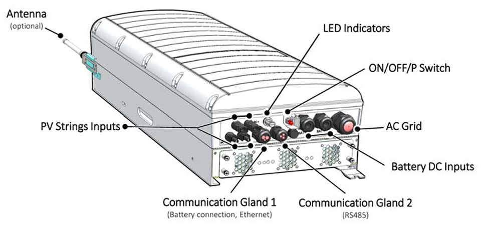
Three-phase inverter: the communication glands are located at the bottom
- Set the ON/OFF/P switch to OFF
- Wait at least 5 minutes (capacitors discharging)
- Turn off the AC protection in the consumer unit
- Remove the hex bolts (or screws) from the cover
- Pull the cover horizontally toward you
After opening, you will see the communication board with the RS485 connectors.
2️⃣ Step 2: Locate the RS485-2 connector
On the communication board, you will find two RS485 ports. We use RS485-2 for the connection to the Currentt Navigator.
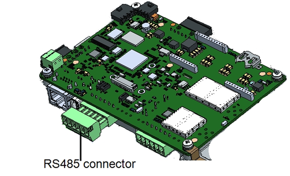
The SolarEdge communication board with the RS485 connector
The connector contains two sets of three pins: RS485-1 (left) and RS485-2 (right). The RS485-2 connector is a green removable terminal block.
Use the three rightmost pins on the connector — this is RS485-2. The left three pins (RS485-1) are reserved for communication with a SolarEdge battery (StorEdge) and must not be used for the Currentt Navigator.
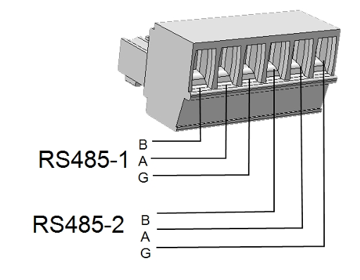
The RS485-1 and RS485-2 connectors with pinout (B, A, G). Use the right three pins (RS485-2).
RS485-2 pinout
The pinout from left to right on the RS485-2 connector:
| Pin | Function | Description |
|---|---|---|
| B (-) | TX-/RX- | Data line B (negative) |
| A (+) | TX+/RX+ | Data line A (positive) |
| G | GND | Reference (ground) |
3️⃣ Step 3: Connect the cable
Use a standard CAT5 or CAT6 (UTP) cable. On the inverter side, cut off the RJ45 connector and strip the individual wires.
Always use a twisted pair for the A and B signal lines. The twisting of the wire pair suppresses electromagnetic interference (EMI) and is essential for a reliable RS485 connection, especially over longer distances.
Wiring
Connect the cable to the RS485-2 terminal block as follows:
| Wire color (T-568B) | RS485-2 connection |
|---|---|
| Blue | A (+) |
| Blue/white | B (-) |
You can also use other wire pairs, as long as you use a twisted pair and are consistent on both ends. The blue/blue-white pair is the standard choice.
Connecting to the Currentt Navigator
The Currentt Navigator has an RS-485 Modbus connector with three pins: A+, B-, and G (ground).
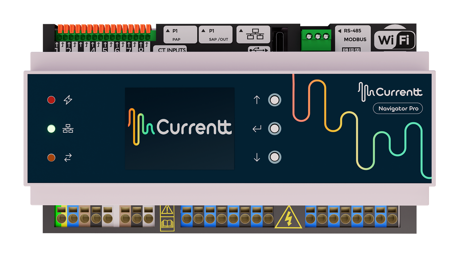
Currentt Navigator Pro: the RS-485 Modbus connector is located at the top right
Connect the other end of the cable to the RS-485 terminal block on the Currentt Navigator:
| Wire color (T-568B) | Currentt Navigator pin | Inverter RS485-2 pin |
|---|---|---|
| Blue | A+ | A (+) |
| Blue/white | B- | B (-) |
Connect the ground on one side only: either to the Currentt Navigator or to the inverter — but never on both sides. Connecting ground on both sides can cause a ground loop, leading to communication errors or equipment damage.
4️⃣ Step 4: Configure the inverter
The configuration differs depending on the inverter type. Modern inverters are configured via the SolarEdge SetApp, older models via the LCD display.
Option A: Configuration via SetApp (modern inverters)
The SetApp is used for all recent SolarEdge inverters (HD-Wave, Home Wave, Home Hub, and recent StorEdge models).
Step 4A.1: Connect to the inverter
- Download the SolarEdge SetApp on your smartphone (iOS/Android)
- Briefly set the ON/OFF/P switch to P (< 2 seconds) and release — the inverter creates a WiFi access point
- Open the SetApp and scan the QR code on the inverter — the app automatically connects to the inverter's WiFi access point
Step 4A.2: Set RS485-2 to SunSpec
Navigate to the communication settings in the SetApp:
- Go to Commissioning > Site Communication
- Tap RS485-2
- Set the following values:
| Setting | Value |
|---|---|
| Protocol | SunSpec (Non-SE Logger) |
| Modbus address (Device ID) | 1 |
| Baud Rate | 115200 |
- Confirm the settings and close the SetApp
Option B: Configuration via LCD display (older inverters)
Older SolarEdge inverters have an LCD display with buttons for navigating through the menu.
Step 4B.1: Open the menu
- Set the ON/OFF/P switch to P and hold it for more than 5 seconds
- The configuration menu appears on the LCD display
- Use the buttons to navigate through the menu
Step 4B.2: Set up server connection
Before configuring RS485-2, first check the server connection:
- Navigate to Communication > Server
- Select a server connection other than RS485 (e.g. Ethernet, Wi-Fi, or None)
If the server communication also runs via RS485, this can conflict with the Modbus RTU connection. Set the monitoring connection to Ethernet or Wi-Fi.
Step 4B.3: Set RS485-2 to SunSpec
- Navigate to Communication > RS485-2 Conf
- Set Device Type to: Non-SE Logger
- Set Protocol to: SunSpec
- Set Device ID to: 1
- Set Baud Rate to: 115200
The menu navigation looks as follows:
Communication
  └── RS485-2 Conf
        ├── Device Type → Non-SE Logger
        ├── Protocol    → SunSpec
        ├── Device ID   → 1
        └── Baud Rate   → 115200
On some older models, the option is called "RS485-1 Conf" instead of "RS485-2 Conf". Check which port you are physically using and select the corresponding menu.
5️⃣ Step 5: Close the inverter and power on
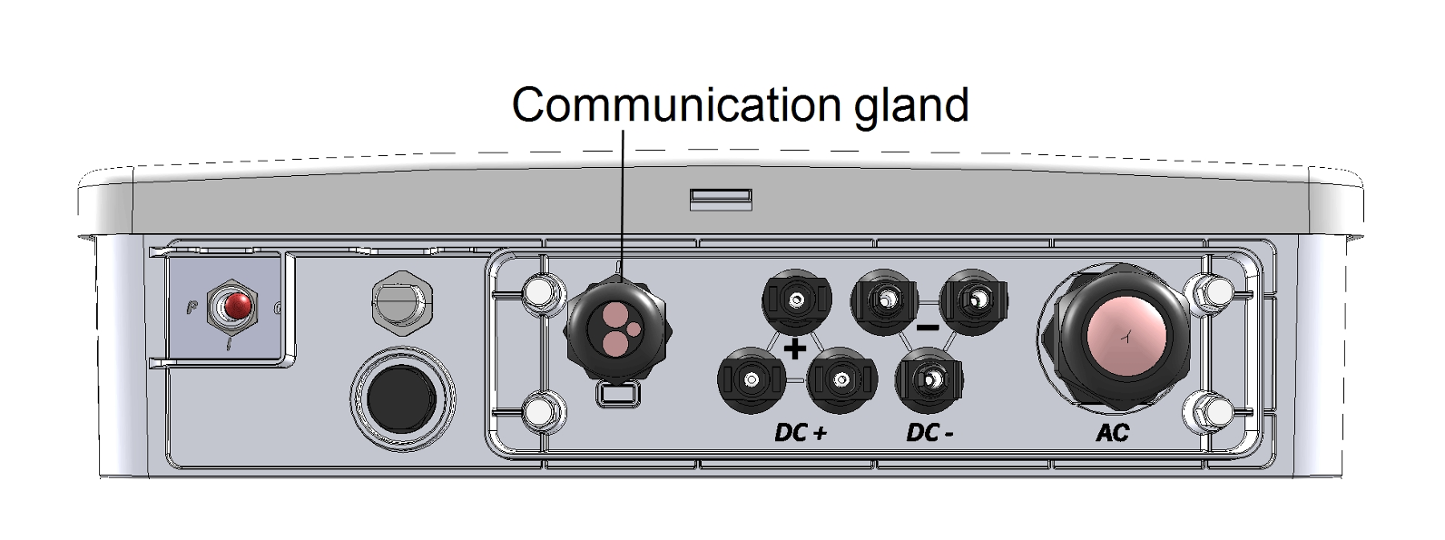
The communication gland (cable gland) at the bottom of the inverter
- Verify that the cable is neatly routed through the communication gland (cable gland)
- Replace the cover and tighten the bolts
- Turn on the AC protection in the consumer unit
- Set the ON/OFF/P switch to ON
- Wait for the inverter to start up (this may take a few minutes)
6️⃣ Step 6: Configuration in the Currentt Navigator
After physically connecting and configuring the inverter, the device must be added in the Currentt Navigator. This can be done in two ways:
🪄 Via the setup wizard (recommended)
- Click the settings icon (top right of the screen)
- Choose Setup Wizard
- Follow the on-screen steps
The setup wizard guides you step by step through the complete configuration process.
Is there a battery connected to the inverter (StorEdge, Home Hub)? Indicate this when the setup wizard asks. This question will automatically appear during the steps.
⚙️ Manual configuration
- Click the settings icon (top right of the screen)
- Go to Components
- Is there a battery connected to the inverter (StorEdge, Home Hub)?
- Yes → Click the + button in the Batteries section
- No → Click the + button in the Inverters section
- Select SolarEdge
- Indicate which phase the inverter is connected to (L1, L2, or L3)
- Under Communication, select Modbus and click RS-485
- Set the communication parameters:
| Parameter | Value |
|---|---|
| Baud Rate | 115200 |
| Data Bits | 8 |
| Parity | None |
| Stop Bits | 1 |
| Modbus address (Device ID) | 1 |
🔗 Connecting multiple inverters (daisy-chain)
If there are multiple SolarEdge inverters at the same location, you can connect them in series (daisy-chain) via RS485:
- Connect the first inverter to the Currentt Navigator via RS485-2 (as described above)
- Connect the RS485-1 port of the first inverter to the RS485-2 port of the second inverter
- Repeat for each additional inverter
- Give each inverter a unique Device ID (1, 2, 3, etc.)
SolarEdge recommends connecting a maximum of 31 devices to an RS485 bus. In practice, we recommend connecting no more than 10 inverters in series for reliable communication.
🔗 Bus topology
Preferably use a daisy-chain (series) topology for the RS485 bus. For short distances (< 25 meters), a star topology often works as well. Connect a maximum of 32 devices to a single RS485 bus.
🔚 Termination resistor
For an RS485 connection, a termination resistor (120 Ohm) must be present at both ends of the bus to prevent signal reflections.
Currentt Navigator
The Currentt Navigator has a built-in termination resistor that can be enabled or disabled via software. By default, it is enabled. For a direct connection between a single inverter and the Currentt Navigator, no changes are needed.
Inverter
SolarEdge inverters have a built-in termination resistor that can be activated with a DIP switch on the communication board. Set the DIP switch to ON on the last inverter in the chain (or the only inverter).

The RS485 DIP switches for termination on the communication board
For a single inverter directly connected to the Currentt Navigator, the termination resistor is active on both sides: the Currentt Navigator (built-in, enabled by default) and the inverter (DIP switch set to ON). This is the ideal configuration.
🛟 Troubleshooting
| Problem | Possible cause | Solution |
|---|---|---|
| No communication | Wiring A/B swapped | Swap the A and B wires |
| No communication | Protocol not set to SunSpec | Check SetApp/display settings |
| No communication | Wrong Device ID | Check that the Device ID matches in the inverter and Navigator |
| Intermittent communication | Poor cable connection | Check that wires are securely fastened in the terminal block |
| Intermittent communication | Cable too long (>1000m) | Use a shorter cable or an RS485 repeater |
| No data after firmware update | SunSpec settings reset | Reconfigure RS485-2 after a firmware update |
| Timeout errors | Wrong baud rate | Ensure the baud rate is 115200 on both sides |
📋 Settings summary
| Parameter | Value |
|---|---|
| Physical port | RS485-2 |
| Protocol | SunSpec (Non-SE Logger) |
| Modbus address (Device ID) | 1 (unique per inverter) |
| Baud Rate | 115200 |
| Data Bits | 8 |
| Parity | None |
| Stop Bits | 1 |
| Cable | CAT5/CAT6 UTP |
| Wire A (+) | Blue |
| Wire B (-) | Blue/white |