CT clamps
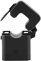
With a CT meter you can measure energy consumption using CT clamps (current transformers). The CT clamps are clamped around the power cables and measure current without requiring a direct electrical connection. This makes installation simple and safe, and is ideal when there is no space in the electrical panel for a DIN-rail meter.
⚙️ How does it work?
A CT clamp is a current transformer that is clamped around a power cable. The clamp measures the magnetic field around the cable and converts it into a small current signal (in milliamps) that is proportional to the current flowing through the cable. The Currentt Navigator reads this signal and calculates the energy consumption from it.
A CT meter is constructed by configuring one or more CT clamps. Each clamp is assigned to a phase (L1, L2, or L3) and connected to an input channel on the Navigator.
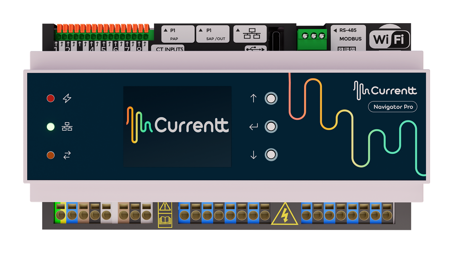
The Currentt Navigator has 8 inputs for CT clamps. This means you can configure up to 8 single-phase meters, or for example 2 three-phase meters and 2 additional single-phase meters (2 x 3 + 2 = 8 channels).
🔌 Connection and color codes
Place the CT clamp with the arrow pointing in the direction of the current flow. The arrow is located on the inside of the clamp. For consumers (e.g. a heat pump), the arrow points towards the heat pump. For generators (e.g. solar panels), the arrow points towards the main grid connection.
| CT clamp wire color | Navigator connector |
|---|---|
| Red or Black | Black (black connector) |
| White | White (white connector) |
Some of the supported CT clamps have a red and a white wire. Connect these to the CT inputs on the Currentt Navigator as described above.
Is the clamp placed in the wrong direction? The direction can also be reversed in software using the Invert clamp direction option.
The wires of the CT clamp must be connected to the Navigator before placing the clamp around the conductor to be measured. Never place a CT clamp around a conductor without the wires being connected.
✅ Supported CT clamps
| Model | Maximum measurable current | Output signal |
|---|---|---|
| SCT-010 | 80A | 40mA |
| SCT-016 | 120A | 40mA |
| ESCT-TA16 | 120A | 40mA |
| SCT-T10 | 80A | 26.6mA |
You cannot use just any CT clamp. Only the models listed below are supported. Every new type of CT clamp must be calibrated by Currentt before it can be used. Contact Currentt if you would like to use a different type.
The SCT-010 supplied by Currentt has been modified with an extra long wire (1 meter) and stripped and tinned wire ends for easy installation.
📋 Configuration
CT meter options
The following options are available when configuring a CT meter:
Name
Give the meter a recognizable name. This helps identify the meter in the overview, especially when multiple meters are configured.
Icon
Choose an icon for the meter. This icon is shown in the overview and helps visually distinguish the meter.
Meter range per phase
Set the metering range per phase. This corresponds to the maximum current that the CT clamp being used can measure. When a metering range is specified, the system can display the meter's load in a visual gauge.
Mode
Determine what the meter measures. The following modes are available:
- Measure energy consumption and generation — The meter measures both energy consumption and energy generation. This is the default setting.
- Measure energy consumption only — The meter measures consumption only. Generation is ignored.
- Measure energy generation only — The meter measures generation only. Consumption is ignored.
- Act as a PAP — Use this meter as a PAP (Primary Allocation Point). This option applies when the meter is used to measure the main grid connection.
Phases (L1, L2, L3)
Select which phases this meter should measure. You can select one, two, or all three phases depending on the installation. For a single-phase connection, select only L1. For a three-phase connection, select L1, L2, and L3.
Measure the sum of the phases
When this option is enabled, the total of all phases determines whether energy is being consumed or generated. This is the default setting.
When this option is disabled, generating phases are counted separately toward production and consuming phases separately toward consumption. This is useful when you want to precisely distinguish between consumption and production per phase.
Use single CT clamp
If the load on the individual phases measured by this meter is always equal, you can use a single clamp instead of an individual clamp for each phase. The measurement from that single clamp is then used for all selected phases.
CT clamp options
Each CT clamp has the following settings:
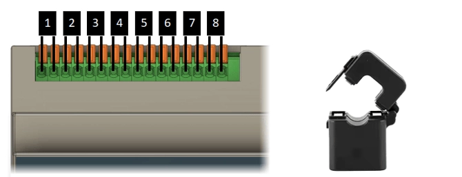
Input channel
Select the input channel on the Currentt Navigator to which the CT clamp is connected. There are 8 inputs available. Each channel corresponds to a physical connector on the Navigator. The input channels for CT clamps are located on the top left of the Navigator.
CT clamp type
Select the type of CT clamp being used. The available options are the supported models listed in the table above. It is important to select the correct type, as the Navigator uses this to apply the correct conversion factor.
Invert clamp direction
Enable this option if the CT clamp is installed in the wrong direction around the cable. We recommend placing the clamp with the arrow pointing in the direction of the current flow. The arrow is located on the inside of the clamp. If the clamp was accidentally placed in reverse, you can correct this in software instead of physically turning the clamp around.
Multiple cable turns
Enable this option if you want to improve accuracy by passing the cable through the CT clamp multiple times. By feeding the cable through the clamp opening multiple times, the measured signal is amplified. This increases the accuracy of the measurement, but the maximum measurable power becomes lower.
🔧 Troubleshooting
| Problem | Possible cause | Solution |
|---|---|---|
| No reading | No input channel selected | Verify that the correct input channel is selected in the clamp settings |
| No reading | CT clamp not connected | Verify that the CT clamp is properly connected to the Navigator |
| Negative values | Clamp in wrong direction | Enable the "Invert clamp direction" option, or physically turn the clamp around |
| Inaccurate reading | Wrong clamp type selected | Verify that the correct CT clamp type is selected |
| Inaccurate reading at low currents | Signal too weak | Use the "Multiple cable turns" option to amplify the signal |