Eastron SDM120 energy meter
This guide describes how to connect an Eastron SDM120 single-phase energy meter for DIN rail mounting (1TE) to the Currentt Navigator via Modbus RTU over RS485.
The Eastron SDM120 is a compact single-phase energy meter for DIN rail mounting. The meter supports bidirectional measurement and communication via Modbus RTU over RS485.

Note: The factory default baud rate on the meter itself may be 2400. The Currentt Navigator uses 9600 by default. Check and change the baud rate on the meter if necessary before configuring communication.
Make sure each device on the RS485 bus has a unique Modbus address.
🔌 Connecting the meter
The meter is connected to the Currentt Navigator using a twisted pair data cable (for example CAT5 or CAT6 UTP). The cable contains two signal lines (A+ and B-) and optionally a ground connection. Always use a twisted pair for the signal lines — the twisting suppresses electromagnetic interference (EMI) and is essential for a reliable RS485 connection.
The RS485 connection is located at the bottom of the meter and consists of two screw terminals:
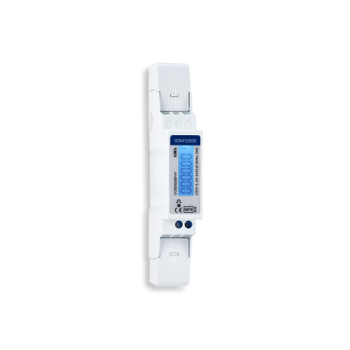
Eastron SDM120 single-phase energy meter
| Terminal | Function | Description |
|---|---|---|
| A+ | TX+/RX+ | Data line A (positive) |
| B- | TX-/RX- | Data line B (negative) |
Connecting the cable
Use a standard CAT5 or CAT6 (UTP) cable. Cut off the RJ45 connector on the meter side and strip the individual wires.
Always use a twisted pair for the A and B signal lines. The twisting of the pair suppresses electromagnetic interference (EMI) and is essential for a reliable RS485 connection, especially over longer distances.
| Wire color (T-568B) | Meter terminal | Currentt Navigator pin |
|---|---|---|
| Blue | A+ | A+ |
| Blue/white | B- | B- |
Connect the ground on one side only: either to the Currentt Navigator or to the meter — but never on both sides. Connecting ground on both sides can cause a ground loop, leading to communication errors or equipment damage.
Bus topology
Preferably use a daisy-chain (series) topology. At short distances (< 25 meters), a star topology often works as well. Connect a maximum of 32 devices to a single RS485 bus. Place a 120 Ohm termination resistor at both ends of the bus.
The Currentt Navigator has a built-in termination resistor that can be enabled or disabled via software. By default, it is enabled.
⚙️ Configuration in the Currentt Navigator
After physically connecting the meter, the device must be added in the Currentt Navigator. This can be done in two ways:
Via the setup wizard (recommended)
- Click the settings icon (top right of the screen)
- Choose Setup wizard
- Follow the on-screen steps
The setup wizard guides you step by step through the complete configuration process.
Manual configuration
- Click the settings icon (top right of the screen)
- Go to Components
- Click the + button in the Meters section
- Select Eastron
- Choose the model SDM120
- Specify what the meter will measure:
- Consumption and generation — the meter measures both consumption and feed-in (bidirectional)
- Consumption only — the meter measures consumption only
- Generation only — the meter measures generation only (for example, behind an inverter)
- Specify which phase the meter is connected to (L1, L2, or L3)
- Under Communication, select RS-485
- Set the communication parameters. The meter's default settings are pre-filled in the Navigator (see settings summary)
Additional options
- Measurement range: If possible, specify the measurement range in amperes that will be measured.
- Reverse meter direction: If the meter is physically installed in the wrong direction, the measurement direction can be reversed in software. This prevents the meter from registering consumption as generation (or vice versa) without physically reversing the meter.
- Use as PAP: This meter can also be used to measure the main connection (PAP, primary allocation point). In that case, select the "Use as PAP" option during configuration.
📋 Settings summary
| Parameter | Value |
|---|---|
| Type | Single-phase energy meter (DIN rail) |
| RS485 terminals | A+ and B- (2 screw terminals) |
| Protocol | Modbus RTU |
| Modbus address | 1 (default, configurable 1-247) |
| Baud Rate | 9600 |
| Data Bits | 8 |
| Parity | None |
| Stop Bits | 1 |
| Bidirectional | Yes |
| Cable | CAT5/CAT6 UTP (twisted pair) |
🔢 Configuring the Modbus address
The default Modbus address of the SDM120 is 1. If multiple meters are connected to the same RS485 bus, each meter must have a unique address.
Via the display
- Press and hold the button for 3 seconds until the display shows "-SET-"
- Enter the default password 1000: the rightmost digit blinks. Press the button briefly to increment the digit. Wait 4 seconds and the next digit begins blinking. Repeat until all 4 digits have been entered
- After entering the password, you enter the settings menu
- Press the button briefly to scroll through the parameters (baud rate, parity, address)
- When the address is displayed, the rightmost digit blinks
- Press the button briefly to increment the digit. Wait 4 seconds for the next digit
- After the last digit, the address is automatically saved
🛟 Troubleshooting
| Problem | Possible cause | Solution |
|---|---|---|
| No communication | Wrong A/B wiring | Swap the A and B wires |
| No communication | Wrong Modbus address | Verify that the address matches in both the meter and the Navigator |
| No communication | Meter not restarted after change | Briefly interrupt the power supply and wait for the meter to restart |
| No communication | Baud rate is set to 2400 (factory default) | Change the baud rate to 9600 via the meter itself |
| No communication | Wrong baud rate | Make sure the baud rate is 9600 on both sides |
| Intermittent communication | Poor cable connection | Verify that wires are securely fastened in the screw terminals |
| Intermittent communication | No twisted pair used | Use a twisted pair for the A and B lines |
| Intermittent communication | Missing termination resistor | Place a 120 Ohm resistor at both ends of the bus |
| Intermittent communication | Star wiring over long distances | Preferably use daisy-chain topology, or shorten the cable distance (< 25 meters) |