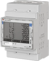
Carlo Gavazzi EM340 energy meter
This guide describes how to connect a Carlo Gavazzi EM340 three-phase energy meter for DIN rail mounting (3TE) to the Currentt Navigator via Modbus RTU over RS485.
The Carlo Gavazzi EM340 is a three-phase energy meter with RS485 Modbus RTU interface.

Carlo Gavazzi follows the TIA-485 standard where A- = inverting (negative) and B+ = non-inverting (positive). This is opposite to most other devices such as the Currentt Navigator, Eastron, Huawei, and SolarEdge, where A = positive and B = negative.
Therefore, connect the Carlo Gavazzi meter as follows:
| Carlo Gavazzi EM340 | Currentt Navigator |
|---|---|
| A- (terminal 9) | B- |
| B+ (terminal 8) | A+ |
| GND (terminal 10) | G |
If you do not swap the wires, communication will not be possible.
Make sure each device on the RS485 bus has a unique Modbus address.
🔀 Variants
The meter is available in two variants:
| Variant | Type | Application |
|---|---|---|
| EM340 ...PFA | Bidirectional | Grid meter (import + export) |
| EM340 ...PFB | Unidirectional | Production meter (import only) |
Use the PFA variant as a grid meter and the PFB variant as a production meter.
🔌 Connecting the meter
The meter is connected to the Currentt Navigator using a twisted pair data cable (for example CAT5 or CAT6 UTP). The cable contains two signal lines (A+ and B-) and optionally a ground connection. Always use a twisted pair for the signal lines — the twisting suppresses electromagnetic interference (EMI) and is essential for a reliable RS485 connection.
The RS485 connection is located on the bottom terminal block of the EM340. The relevant terminals are:
| Terminal | Function | Description |
|---|---|---|
| 7 | T | Termination (termination resistor) |
| 8 | B+ | Data line B (positive) |
| 9 | A- | Data line A (negative) |
| 10 | GND | Reference (earth) |
Carlo Gavazzi EM340: RS485 terminals (7=T, 8=B+, 9=A-, 10=GND)
Always use a twisted pair for the A and B signal lines. The twisting of the pair suppresses electromagnetic interference (EMI) and is essential for a reliable RS485 connection, especially over longer distances.
Connect the ground on one side only: either to the Currentt Navigator or to the meter — but never on both sides. Connecting ground on both sides can cause a ground loop, leading to communication errors or equipment damage.
Termination (termination resistor)
If the EM340 is the last device in the RS485 chain, connect terminal 7 (T) to terminal 9 (A-). This activates the built-in termination resistor (120 Ohm).
Note: A/B are swapped!
Carlo Gavazzi uses the TIA-485 convention: A- = negative, B+ = positive. This is opposite to the naming on the Currentt Navigator. Connect the wires as follows:
| Carlo Gavazzi EM340 | Currentt Navigator |
|---|---|
| A- (terminal 9) | B- |
| B+ (terminal 8) | A+ |
Remember: EM340 A- goes to Navigator B-, and EM340 B+ goes to Navigator A+. The names are opposite, but the polarity must match.
Bus topology
Preferably use a daisy-chain (series) topology. At short distances (< 25 meters), a star topology often works as well. Connect a maximum of 32 devices to a single RS485 bus. Place a 120 Ohm termination resistor at both ends of the bus.
The Currentt Navigator has a built-in termination resistor that can be enabled or disabled via software. By default, it is enabled.
⚙️ Configuration in the Currentt Navigator
After physically connecting the meter, the device must be added in the Currentt Navigator. This can be done in two ways:
Via the setup wizard (recommended)
- Click the settings icon (top right of the screen)
- Choose Setup wizard
- Follow the on-screen steps
Manual configuration
- Click the settings icon (top right of the screen)
- Go to Components
- Click the + button in the Meters section
- Select Carlo Gavazzi
- Choose the model EM340
- Specify what the meter will measure:
- Consumption and generation — the meter measures both consumption and feed-in (bidirectional)
- Consumption only — the meter measures consumption only
- Generation only — the meter measures generation only (for example, behind an inverter)
- Specify which phases the meter is connected to (L1, L2, and/or L3)
- Under Communication, select RS-485
- Set the communication parameters. The meter's default settings are pre-filled in the Navigator (see settings summary)
Additional options
- Measurement range: If possible, specify the measurement range in amperes that will be measured.
- Reverse meter direction: If the meter is physically installed in the wrong direction, the measurement direction can be reversed in software. This prevents the meter from registering consumption as generation (or vice versa) without physically reversing the meter.
- Use as PAP: This meter can also be used to measure the main connection (PAP, primary allocation point). In that case, select the "Use as PAP" option during configuration.
📋 Settings summary
| Parameter | Value |
|---|---|
| Brand | Carlo Gavazzi |
| Model | EM340 |
| Type | Three-phase energy meter |
| Baud rate | 9600 |
| Data bits | 8 |
| Parity | None |
| Modbus address | 1 (default) |
| Terminal 7 | T (termination) |
| Terminal 8 | B+ (→ Navigator A+) |
| Terminal 9 | A- (→ Navigator B-) |
| Terminal 10 | GND |
🔢 Setting the Modbus address
The EM340 is shipped with Modbus address 1 by default. The address can be changed via:
Via the display
- Press and hold the Enter key (SET) for 2 seconds to enter programming mode
- Use the arrow key to navigate through the menu items. Scroll past the PASS (password) menu
- Navigate until the "Addr" (Address) menu appears
- Press and hold the Enter key for 2 seconds to edit the address
- Use the arrow keys to set the desired address (001-247)
- Confirm the setting with the Enter key
🛟 Troubleshooting
| Problem | Possible cause | Solution |
|---|---|---|
| No communication | A/B wires not swapped | Swap A and B: EM340 A- → Navigator B-, EM340 B+ → Navigator A+ |
| No communication | Wrong Modbus address | Verify that the address matches in both the meter and the Navigator |
| No communication | Parity is enabled on the meter | Set parity to None (disabled) |
| Incorrect readings | Wrong word order (MSW-LSW instead of LSW-MSW) | Check if the meter is a production unit (ID 341) and set LSW-MSW |
| Energy values are a factor of 10 too high | Values not divided by 10 | Energy values are kWh x 10; divide by 10 |
| Intermittent communication | No twisted pair used | Use a twisted pair for the signal lines |
| Intermittent communication | Termination missing | Connect terminal 7 (T) to terminal 9 (A-) on the last device |
| Timeout errors | Wrong baud rate | Make sure the baud rate is 9600 on both sides |