Phoenix Contact EEM-EM357 energy meter
This guide describes how to connect a Phoenix Contact EEM-EM357 three-phase energy meter for DIN rail mounting (4TE) to the Currentt Navigator via Modbus RTU over RS485.
The Phoenix Contact EEM-EM357 is a three-phase energy meter with RS485 Modbus RTU interface. The meter is widely used in industrial environments and offers extensive measurement capabilities.

Phoenix Contact uses the TIA-485 standard where A- = inverting (negative) and B+ = non-inverting (positive). This is opposite to most other devices such as the Currentt Navigator, Eastron, Huawei, and SolarEdge, where A = positive and B = negative.
Therefore, connect the Phoenix Contact meter as follows:
| Phoenix Contact EEM-EM357 | Currentt Navigator |
|---|---|
| A- (terminal 2) | B- |
| B+ (terminal 3) | A+ |
If you do not swap the wires, communication will not be possible.
The default Modbus address of the EEM-EM357 is 5, not 1 as with most other meters. Keep this in mind during configuration.
Make sure each device on the RS485 bus has a unique Modbus address.
🔌 Connecting the meter
The meter is connected to the Currentt Navigator using a twisted pair data cable (for example CAT5 or CAT6 UTP). The cable contains two signal lines (A+ and B-) and optionally a ground connection. Always use a twisted pair for the signal lines — the twisting suppresses electromagnetic interference (EMI) and is essential for a reliable RS485 connection.
The RS485 connection is located on the terminal strip of the EEM-EM357. The relevant terminals are:
| Terminal | Function | Description |
|---|---|---|
| 1 | NC / Shield | Not connected / shielding |
| 2 | A- | Data line A (negative) |
| 3 | B+ | Data line B (positive) |
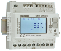
Phoenix Contact EEM-EM357: RS485 terminals (1=NC/Shield, 2=A-, 3=B+)
Always use a twisted pair for the A and B signal lines. The twisting of the pair suppresses electromagnetic interference (EMI) and is essential for a reliable RS485 connection, especially over longer distances.
Connect the ground on one side only: either to the Currentt Navigator or to the meter — but never on both sides. Connecting ground on both sides can cause a ground loop, leading to communication errors or equipment damage.
Connecting the cable
| Phoenix Contact EEM-EM357 | Currentt Navigator |
|---|---|
| A- (terminal 2) | B- |
| B+ (terminal 3) | A+ |
Bus topology
Preferably use a daisy-chain (series) topology. At short distances (< 25 meters), a star topology often works as well. Connect a maximum of 32 devices to a single RS485 bus. Place a 120 Ohm termination resistor at both ends of the bus.
The Currentt Navigator has a built-in termination resistor that can be enabled or disabled via software. By default, it is enabled.
⚙️ Configuration in the Currentt Navigator
After physically connecting the meter, the device must be added in the Currentt Navigator. This can be done in two ways:
Via the setup wizard (recommended)
- Click the settings icon (top right of the screen)
- Choose Setup wizard
- Follow the on-screen steps
Manual configuration
- Click the settings icon (top right of the screen)
- Go to Components
- Click the + button in the Meters section
- Select Phoenix Contact
- Choose the model EEM-EM357
- Specify what the meter will measure:
- Consumption and generation — the meter measures both consumption and feed-in (bidirectional)
- Consumption only — the meter measures consumption only
- Generation only — the meter measures generation only (for example, behind an inverter)
- Specify which phases the meter is connected to (L1, L2, and/or L3)
- Under Communication, select RS-485
- Set the communication parameters. The meter's default settings are pre-filled in the Navigator (see settings summary)
Additional options
- Measurement range: If possible, specify the measurement range in amperes that will be measured.
- Reverse meter direction: If the meter is physically installed in the wrong direction, the measurement direction can be reversed in software. This prevents the meter from registering consumption as generation (or vice versa) without physically reversing the meter.
- Use as PAP: This meter can also be used to measure the main connection (PAP, primary allocation point). In that case, select the "Use as PAP" option during configuration.
📋 Settings summary
| Parameter | Value |
|---|---|
| Brand | Phoenix Contact |
| Model | EEM-EM357 |
| Type | Three-phase energy meter |
| Baud rate | 9600 |
| Data bits | 8 |
| Parity | None |
| Modbus address | 5 (default) |
| Programming password | 1000 (default) |
| Terminal 1 | NC / Shield |
| Terminal 2 | A- (→ Navigator B-) |
| Terminal 3 | B+ (→ Navigator A+) |
🛟 Troubleshooting
| Problem | Possible cause | Solution |
|---|---|---|
| No communication | A/B wires not swapped | Swap A and B: EEM-EM357 A- → Navigator B-, EEM-EM357 B+ → Navigator A+ |
| No communication | Modbus address is set to 1 instead of 5 | Set the address in the Navigator to 5 (factory default of the meter) |
| No communication | Wrong Modbus address | Verify that the address matches in both the meter and the Navigator |
| No communication | Parity is enabled on the meter | Set parity to None (disabled) |
| Intermittent communication | No twisted pair used | Use a twisted pair for the signal lines |
| Intermittent communication | Termination missing | Enable the termination resistor on the last device in the chain |
| Timeout errors | Wrong baud rate | Make sure the baud rate is 9600 on both sides |
| Settings cannot be changed | Programming password incorrect | Default password is 1000 |